

01. New Test File: TF-4828
02. Updated Test File: FSoE TF-2602
03. CTT performance improvements for test loading and execution
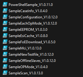
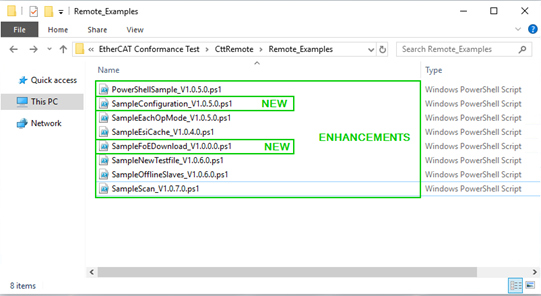
04. Revised PowerShell examples
05. Support of FSoE ESI-Modules with Identical ID and CRC
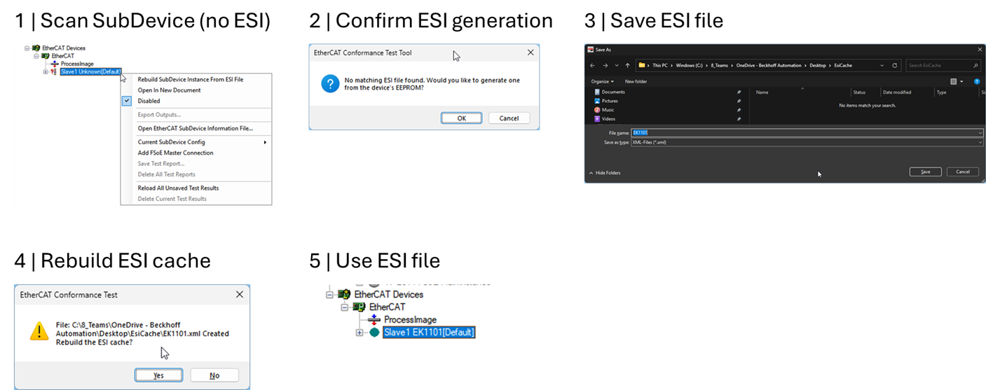
06. Generate an ESI file from SII of SubDevice
07. Include latest EtherCATInfo.xsd
08. Enhancements and bug fixes
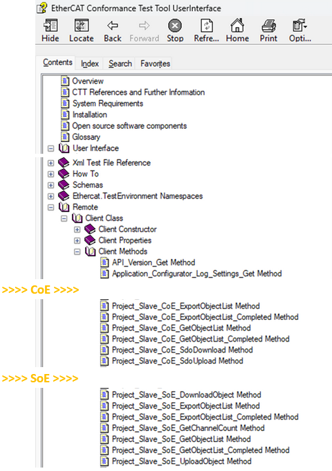
01. CTT remote control: “CoE and SoE online tab functions” available
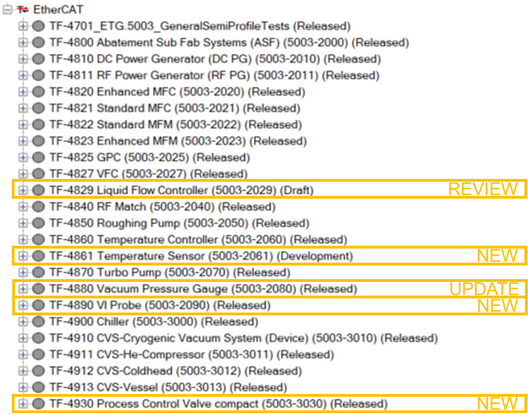
02. Test Files (TF)
03. Enhancements and bug fixes in the CTT and test files
01. Windows command line control
02. FSoE MainInstance tests
03. Minor bug fixes and improvements
01. Test File Update
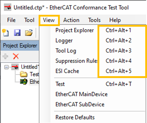
02. Navigate by keyboard
03. Export Results Overview
04. FSoE MainInstance tests – draft status
01. New and updated files
02. FSoE MainDevice testing
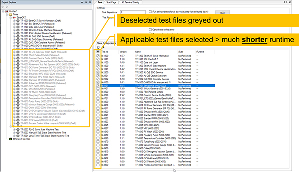
03. Test selection: files, groups, cases
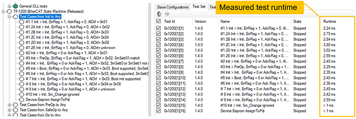
04. Test case runtime
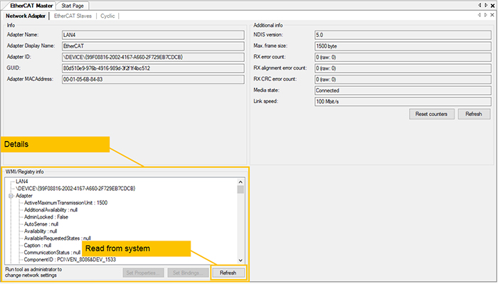
05. Network adapter details
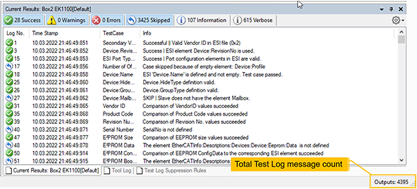
06. Output message number
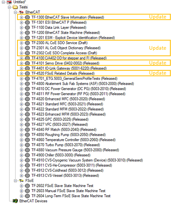
01. Test Files: Overview of updates and new tests
02. New Tab: Diagnosis
03. New Tab: AoE Online
04. New Tab: FoE Online
05. New Tab: EtherCAT Master
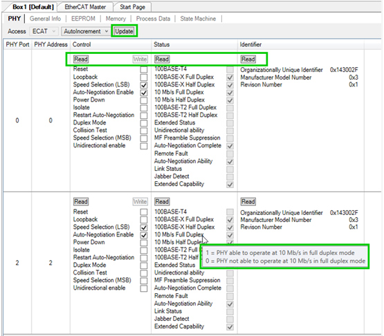
06. New Tab: PHY
07. Recalculate Module@Crc32 for FSoE modules
08. Export test results
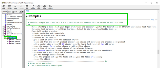
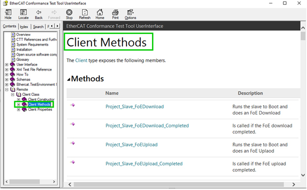
09. Enhanced CTT Remote Control Interface methods and documentation
10. EtherCATInfo Schema file
01. Test Files: Overview of updates and new tests
02. Tools | CRC Verifier
03. Tools | CTT Report
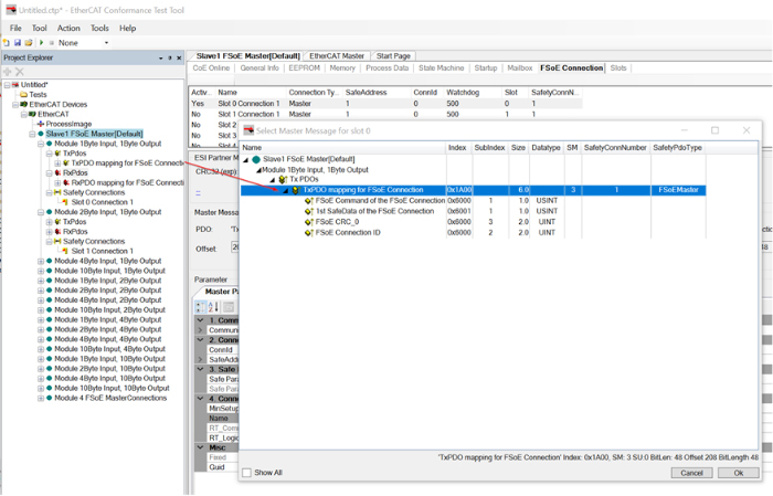
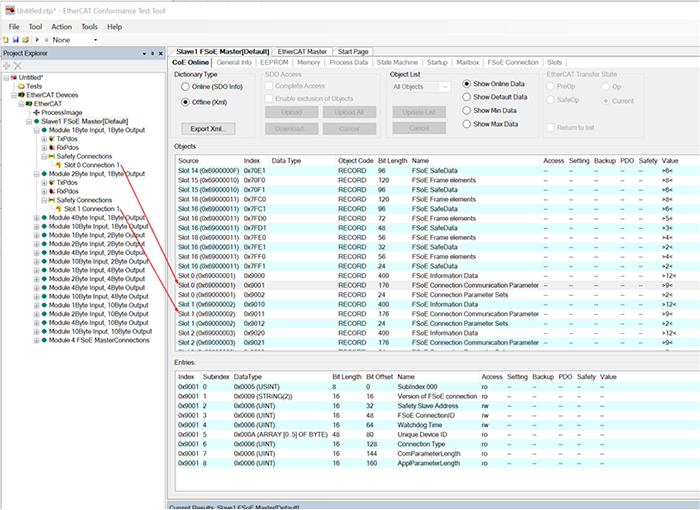
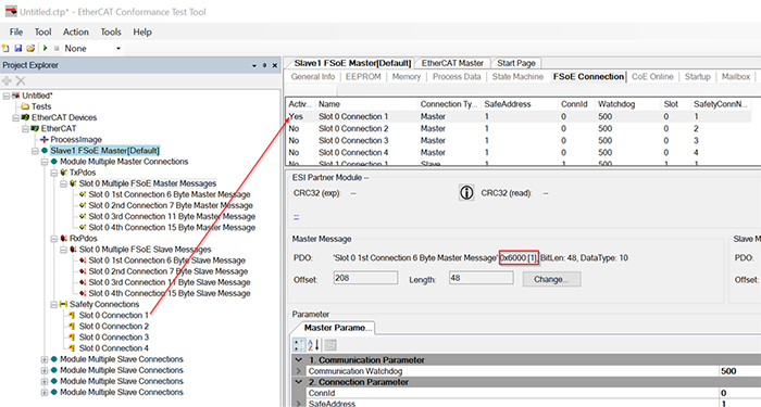
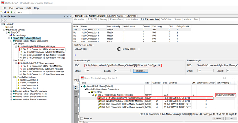
04. Support of multiple FSoE Connections
05. Init Cmd Import for config (feature under preparation)
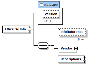
06. EtherCATInfo Schema file
07. EtherCAT Configurator: Copy and Paste for slave configurations
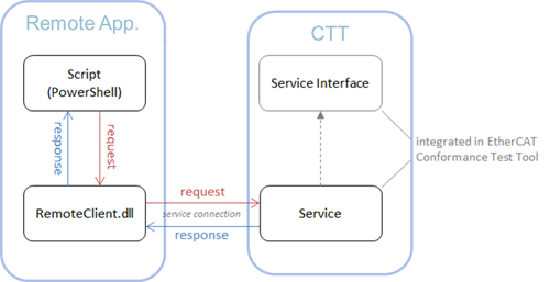
08. CTT Remote Control Interface
09. Update of ESI Editor Control
01. Slave Configurations
02. Automatical Generation of possible Module Configurations
03. DC Modes
04. Edit Cycle Times per Configuration
05. Activate Configuration
06. Run Tests for all Configurations
07. Calculation of Module CRC (for ESI element Modules:Module@Crc32)
08. Generation of CRC Calculation File
09. Configure several FSoE Connections
01. Offline Test
02. Test Different Configurations
03. Module/Slots
04. Real Time Mode
05. FSoE
06. State Machine
07. Update of Test Set
08. Memory View
09. EEPROM Update via Drag and Drop
10. Offline OD Generation
11. Start-Up Commands
12. Report Generation
13. Result Export
14. Tool Log
15. ESI Repository Location

Update of TF-2602 to version 1.5.1.0. To compare results also V1.5.0. is included which will be removed after review.

$:\Program Files (x86)\EtherCAT Conformance Test\CttRemote\PS\Examples
ModuleIdent is unique in case of FSoE and per VendorId. However, if value in ESIModule/@Crc are identical and correct, identical ModuleIdent values may occur multiple times. While this is not recommended in general, it allows for certain backward compatibility reasons.
Scan the SubDevice and generate the ESI file based on the information the CTT reads from the SII.
Latest *.xsd schema version is 1.21.
ESI schema enhancement:
See CTT and test file history and comment resolution.
The SDO Information services and SDO upload services (respective for SoE) are available via the remote-control interface. The methods are described in the help file:
See CTT and test file history and comment resolution.
CTT can be started via the Windows command line. All remote control functions are now available via the command line, too.
Start the ECConformanceTest.Console.exe in the installation folder. Integrate the CTT into your development and test process by making use of the command line feature for your pipelines (e.g., Microsoft Azure DevOps™).
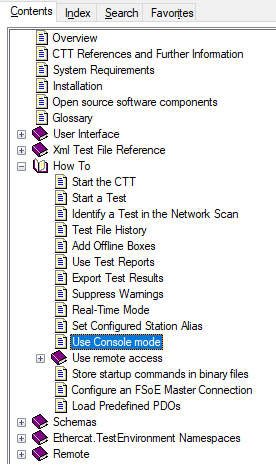
See also the help file (F1) and navigate to the How To chapter “Use Console mode”
The FSoE MainInstance tests are now about to be released in cooperation with TÜV Süd. They are part of the CTT installation and can be added manually. Those tests are a significant help for the development and certification with a notified body.
Important: With those tests becoming official, a dedicated license file for FSoE MainInstance tests is required to run the MainInstance test files.
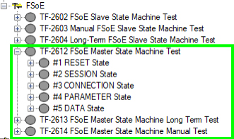
NOTE: Information on how to obtain an FSoE MainInstance license will be provided separately.
Get a CSV or XLSX file with a detailed overview with a test result for each test case and test slave individually. Used for documentation and for comparison of test results.
Navigate to Tool > Export Results Overview...
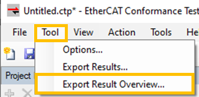
Open the file:

FSoE MainInstance test files are included in the CTT V2.5 setup.

Add them by right click on Tests and select the test file set...
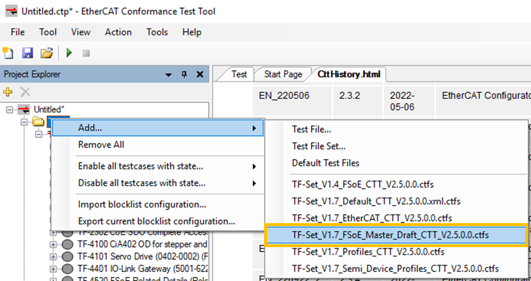
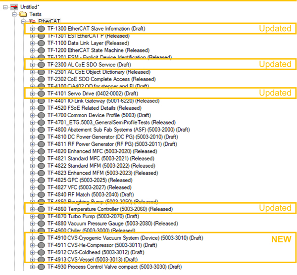
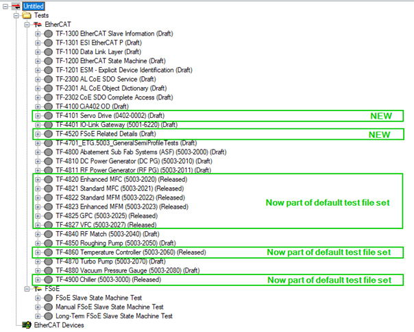
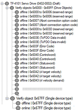
Focus on tests beyond TF-4101 based on CiA402 drive profile according to ETG.6010 / CiA402 / IEC61800-7
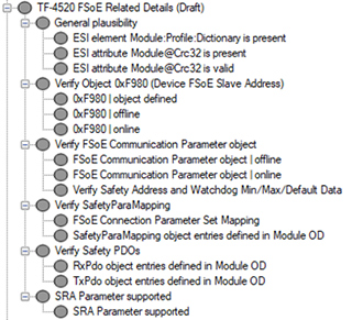
Focus on general structure, mandatory and recommended Safety over EtherCAT features according to Safety over EtherCAT Protocol Enhancements (ETG.5120) and EtherCAT Slave Information specification (ETG.2000).
Test files TF-4820, TF-4821, TF-4822, TF-4823, TF-4825, TF-4827, TF-4860 and TF-4900 are now part of default test file set.
Bugfixes and enhanced test coverage. See “Test file” [right-click] > “View History…” for more information.
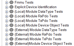
Test group has been moved to test file TF-1201 with other tests relevant to explicit device identification.
The new tab “Diagnosis” provides an interface for the Diagnosis History Object 0x10F3. Diagnosis messages (0x10F3 SI6 - 255), related information (0x10F3 SI1 – 4), and flags (0x10F3 SI5) are decoded by the new CTT.
Use:
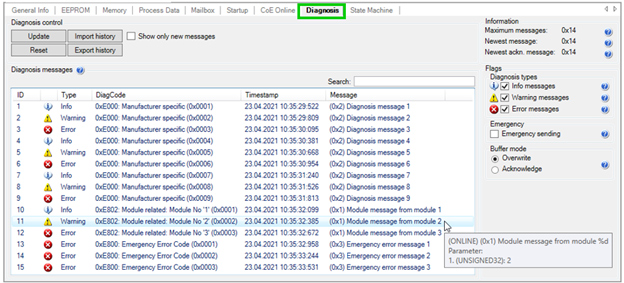
Interface features:
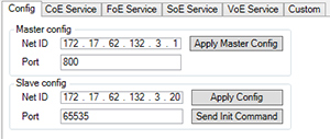
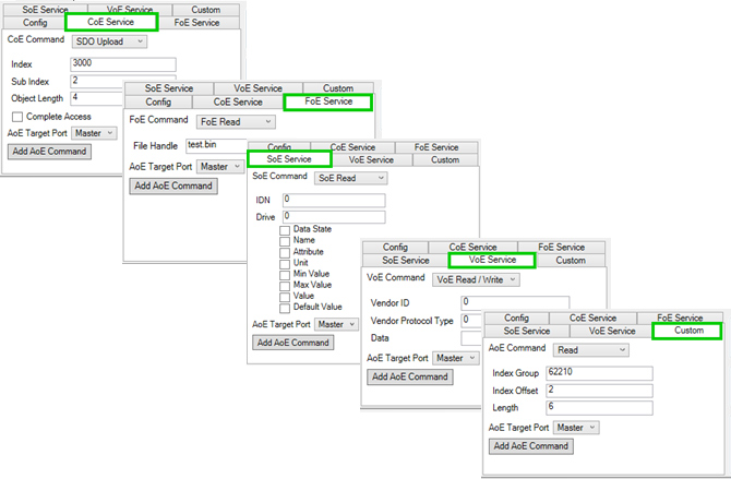
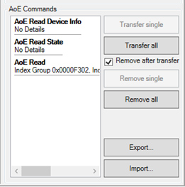
The new tab “AoE Online” (ADS over EtherCAT) provides an interface for sending AoE requests and receiving AoE responses.
Use:
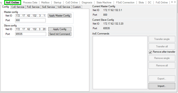
Interface features:
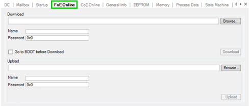
The new tab “FoE Online” (File access over EtherCAT) provides an interface for FoE downloads and FoE uploads.
Use:
New “EtherCAT Master” tab with additional information on:
a) Network adapter
b) EtherCAT slaves
c) Cyclic commands
Use:
Interface features include:

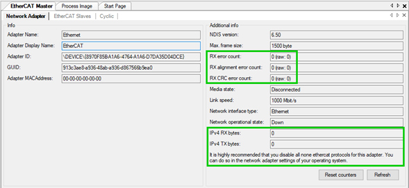
Use:
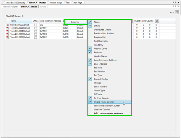
Interface features include:
Use:

Access to PHY registers 0x0510:0x0515.
Use:
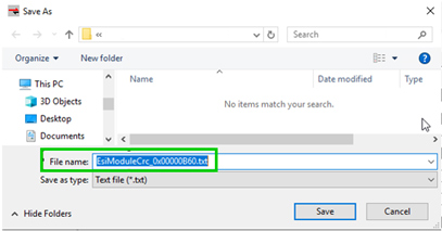
The Module@Crc32 from ESI file and the expected (i.e. correct) one is displayed. In case Crc32 in ESI file is wrong, button “Recalculate” allows to generate a text file which lists the result of each individual calculation step:

Select text file path for output:
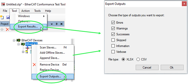
Export test results in *.xlsx or *.csv format.
Use:
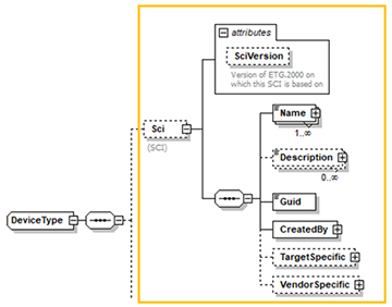
Latest EtherCATInfo.xsd (www.ethercat.org/etg2000) schema file. It includes the Slave Configuration Interface (SCI) description.
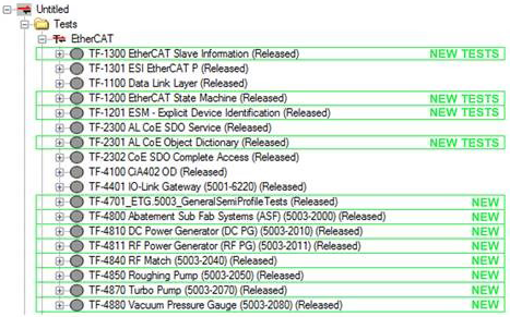
Basic Physical Layer Test of Ethernet channel

Focus on Explicit Device Identification and testing ESI files with element Modules
Focus on objects in the Communication specific range (0x1000…0x1FFF)
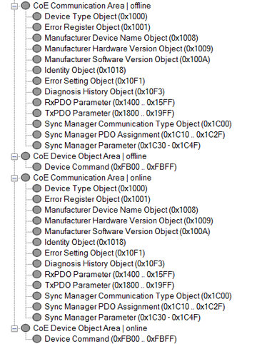
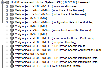
Focus on Semi Device Profile ETG.5003 CDP Requirements

Semi Device Profile Test for different SDPs, including 2000, 201x, 2040, 2050, 2070, 2080. The test all object and object entry attributes in all index ranges in the offline and online dictionary. Example shown below for profile 2000 ASF:
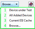
Menu bar “Tools”: Module CRC Verifier

Select ESI from different sources
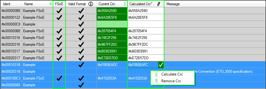
Verification of FORMAT and CRC

CRC can be
Recalculated
Edited
Removed
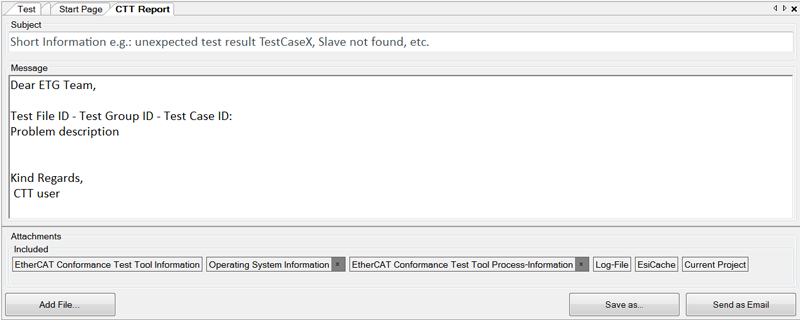
Menu bar “Tools”: CTT Report

Email Template with all attachments
Multiple Connections per Slave
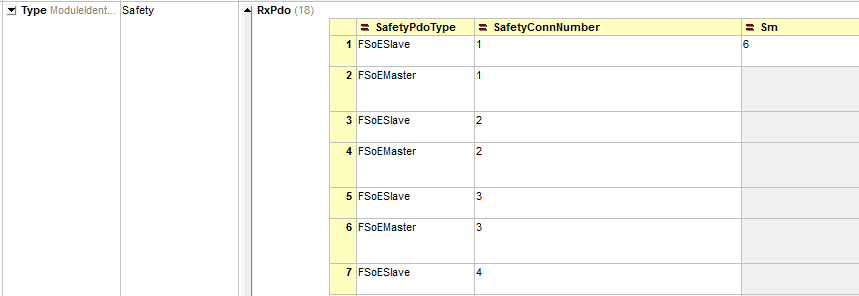
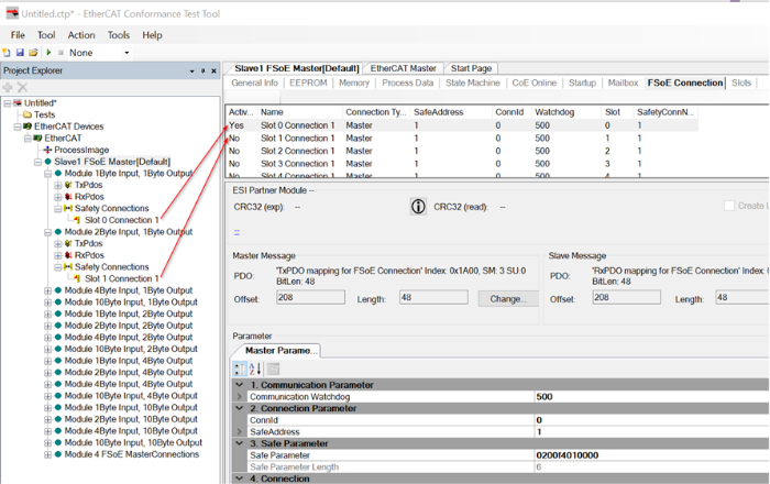
For testing an individual connection of one slave, a slave configuration is generated. On this active connection the FSoE tests are performed.
EtherCAT Configurator: Import of Mailbox Init Commands:
Allows to provide a specific list of start-up commands via a binary file
Within the slave configuration it is possible to include the binary file so that the start-up commands are loaded to the configuration and sent to the DuT before test file execution
Latest EtherCATInfo.xsd (www.ethercat.org/etg2000) schema file. It also includes EtherCAT P elements.
Slave configurations can be copied
Directly

Via xml editor changes
Copy and paste Slave Configuration to XML editor

Edit,copy and paste to Slave Configuration list
Including Documentation and Example
Uses Windows Communication Framework
Depending on service settings, uses different services (http, TCP) to connect, also on local machine.
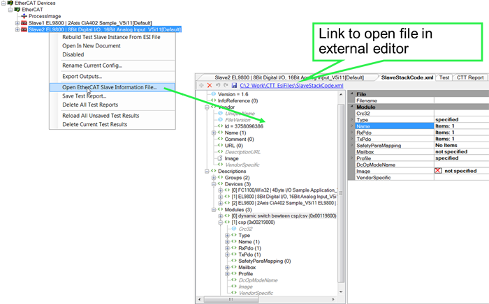
Open ESI editor via context menu
EtherCAT slaves can have either fixed or flexible configurations, including their process data, synchronization modes (SyncManager-synchronous, DC-synchronous, …) and other:
Fixed configuration: process data, sync modes, etc. cannot be changed
Flexible configuration: process data, modules, sync modes, start-up commands, etc. can be changed from the default configuration
The CTT can be used to generate different configurations based on the slave’s ESI file.
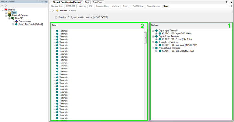
The following screenshot shows the available modules in the right green field (1), listing different possible modules: KL1002, KL2012, KL3001, KL4001. The Default configuration of this example, a bus coupler, is that no modules are configured (2).
On the tab “Test” the available “Slave Configurations” for the bus coupler are listed. By default only one:

To test the bus coupler with each of the four possible module configurations at least once, the CTT supports their generation as shown below:
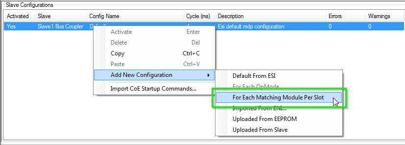
All automatically generated slave configurations are then listed in the “Slave Configurations” window:

With the help of CTT, different Synchronization Mode configurations can be generated automatically. Below a slave with four DC modes is shown:

As shown below, an individual, per OP-mode configuration can be generated:
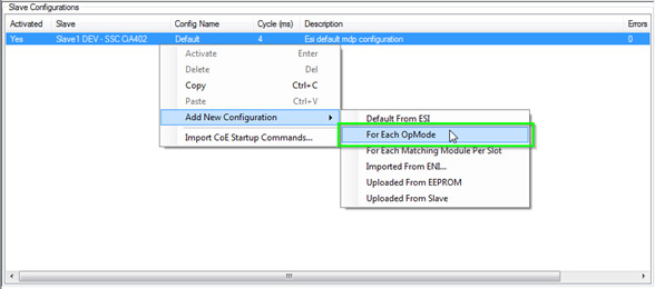
For each OpMode of the slave a configuration is generated (also, the Default configuration is still listed which is basically redundant with “noDc”):

Cycle Times can be edited for each configuration individually. Double-click on the cycle time field:

Individual configurations can be activated as shown below. Changes on other tabs (e.g. start-up commands) always apply for the active configuration.

With activating the “Run test cases for selected configurations” the CTT will run each test file for each configuration.

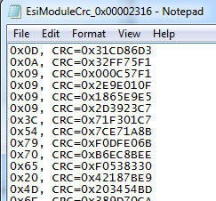
For ESI files which use the attribute Module@Crc32 (e.g. FSoE slaves) the CTT displays the CRC as given in the ESI file vs. the expected one.

The CTT generates a *.txt file with the CRC32 calculation sequence in the ESI File folder.

The *.txt file has the sequence of the CRC calculation:
The CTT supports slaves with one or even several FSoE connections.

Slave devices can be added offline to test the ESI file only.

Select one or several devices to add to the offline configuration.

And run all offline tests to test the ESI file.
Different slave configurations can be tested – with different process data, Distributed Clock settings, module configurations, etc.

Configure the modules of the slave and test it:

In CTT Version 1.x.x tests could not be performed for devices running Distributed Clocks (DC) mode and had to be done manually. With the integrated driver in CTT Version 2 and the real-time hardware extension (CU2508) manual testing is obsolete – it is replaced by automated testing.
Compared to the previous need of manual testing (along ETG.7000-2AnnexA Testing for Devices in DC Mode) for both, in-house testing as well as at the ETC, the automated testing saves considerable time. Also, long-term-testing and automated testing of the DuT in different DC configurations is now possible without manual intervention.
The fact, that in-house testing and testing at the ETC can happen with the same set-up, test results also become even more transparent.
The CU2508 needs to be obtained only once while CTT Version 2 also runs on any Windows PC utilizing any standard NIC support 1GBit/s.
CTT Version 1 and CTT Version 2 – for devices not supporting DC modes:

CTT Version 2 - with real-time hardware extension to perform all tests also for DuTs running in DC mode:

The FSoE Conformance Test Tool functionality is now integrated with the EtherCAT Conformance Test Tool and is simply activated with the additional FSoE Conformance Test license file.

Use the CTT to step through the EtherCAT states.

A significant number of tests have been added to help you with finding and fixing the little details.
Test Groups with new tests:
The ESC registers can be read from the slave and are shown in a well-readable and well-interpreted way.

Drag and drop an ESI file to the EEPROM control to view it and press “Write” to write the SII of the device.

Upload the online Object Dictionary from the device and save it as offline Object Dictionary to add it to the ESI file element Device:Profile:ObjectDictionary.

The CTT generates the necessary start-up commands – a previous ENI file import is not necessary any more.

Store the test report with all tests, results, and device information. The reports can be opened using the CTT.

The report/s is/are shown when expanding the device:

Export the test results to a csv or xml file for your documentation.

Get a spreadsheet with a result summary and individual test reports.

The tool log reports the CTT’s performed steps and may also report additional issues with the device or its ESI file.

Set the ESI repository location to any file path convenient for working with the CTT.
![]()