
EtherCAT - the Ethernet Fieldbus
This section provides an in-depth introduction into EtherCAT (Ethernet for Control Automation Technology). The following information can also be found the the EtherCAT Brochure, available in various languages.
EtherCAT is a real-time Industrial Ethernet technology originally developed by Beckhoff Automation. The EtherCAT protocol which is disclosed in the IEC standard IEC61158 is suitable for hard and soft real-time requirements in automation technology, in test and measurement and many other applications.
The main focus during the development of EtherCAT was on short cycle times (≤ 100 µs), low jitter for accurate synchronization (≤ 1 µs) and low hardware costs.
EtherCAT was introduced in April 2003, and the EtherCAT Technology Group was founded in November 2003 - Meanwhile ETG has grown into the world’s largest Industrial Ethernet and fieldbus organization. The ETG brings together manufacturers and users, which contribute in technical working groups to the advancement of the EtherCAT technology.
1. Features of EtherCAT
1.1 Functional Principle1.2 The EtherCAT Protocol
1.3 Flexible Topology
1.4 EtherCAT P
1.5 High-Precise Synchronization
1.6 Diagnosis and Error Localization
1.7 High Availability Requirements
1.8 Safety over EtherCAT
1.9 Communication Profiles
1.9.1 CAN Application Protocol over EtherCAT (CoE)
1.9.2 Servo Drive Profile according to IEC 61491-7-204 over EtherCAT (SoE)
1.9.3 Ethernet over EtherCAT (EoE)
1.9.4 File Access over EtherCAT (FoE)
1.9.5 ADS over EtherCAT (AoE)
1.10 EtherCAT Automation Protocol (EAP)
1.11 Integration of other Bus Systems
1.12 EtherCAT, TSN, Industrie 4.0 and IoT
2. Implementing EtherCAT Interfaces
2.1 MainDevice2.2 SubDevice
3. Conformance and Certification
3.1 Plug Fest3.2 Conformance Test Tool
3.3 Technical Working Group Conformance
3.4 EtherCAT Test Center
4. International Standardization
1.1 Functional Principle
The EtherCAT MainDevice sends a telegram that passes through each node. Each EtherCAT SubDevice reads the data addressed to it “on the fly”, and inserts its data in the frame as the frame is moving downstream. The frame is delayed only by hardware propagation delay times. The last node in a segment (or drop line) detects an open port and sends the message back to the MainDevice using Ethernet technology’s full duplex feature.
The telegram’s maximum effective data rate increases to over 90 %, and due to the utilization of the full duplex feature, the theoretical effective data rate is even higher than 100 Mbit/s (> 90 % of two times 100 Mbit/s).
The EtherCAT MainDevice is the only node within a segment allowed to actively send an EtherCAT frame; all other nodes merely forward frames downstream. This concept prevents unpredictable delays and guarantees real-time capabilities.
The MainDevice uses a standard Ethernet Media Access Controller (MAC) without an additional communication processor. This allows a MainDevice to be implemented on any hardware platform with an available Ethernet port, regardless of which real-time operating system or application software is used. EtherCAT SubDevices use an EtherCAT SubDevice Controller (ESC) to process frames on the fly and entirely in hardware, making network performance predictable and independent of the individual SubDevice implementation.
1.2 The EtherCAT Protocol
EtherCAT embeds its payload in a standard Ethernet frame. The frame is identified with the Identifier (0x88A4) in the EtherType field. Since the EtherCAT protocol is optimized for short cyclic process data, the use of protocol stacks, such as TCP/IP or UDP/IP, can be eliminated.
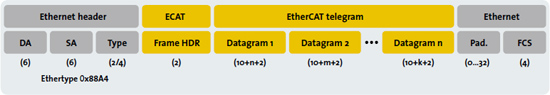
EtherCAT in a standard Ethernet frame (according to IEEE 802.3)
To ensure Ethernet IT communication between the nodes, TCP/IP connections can optionally be tunneled through a mailbox channel without impacting real-time data transfer.
During startup, the MainDevice configures and maps the process data on the SubDevices. Different amounts of data can be exchanged with each SubDevice, from one bit to a few bytes, or even up to kilobytes of data.
The EtherCAT frame contains one or more datagrams. The datagram header indicates what type of access the MainDevice would like to execute:
- Read, write, read-write
- Access to a specific SubDevice through direct addressing, or access to multiple SubDevices through logical addressing (implicit addressing)
Logical addressing is used for the cyclical exchange of process data. Each Datagram addresses a specific part of the process image in the EtherCAT segment, for which 4GBytes of address space is available. During network startup, each SubDevice is assigned one or more addresses in this global address space. If multiple SubDevices are assigned addresses in the same area, they can all be addressed with a single Datagram. Since the Datagrams completely contain all the data access related information, the MainDevice can decide when and which data to access. For example, the MainDevice can use short cycle times to refresh data on the drives, while using a longer cycle time to sample the I/O; a fixed process data structure is not necessary. This also relieves the MainDevice in comparison to in conventional fieldbus systems, in which the data from each node had to be read individually, sorted with the help of the process controller, and copied into memory.
With EtherCAT, the MainDevice only needs to fill a single EtherCAT frame with new output data, and send the frame via automatic Direct Memory Access (DMA) to the MAC controller. When a frame with new input data is received via the MAC controller, the MainDevice can copy the frame again via DMA into the computer’s memory – all without the CPU having to actively copy any data. In addition to cyclical data, further Datagrams can be used for asynchronous or event driven communication.
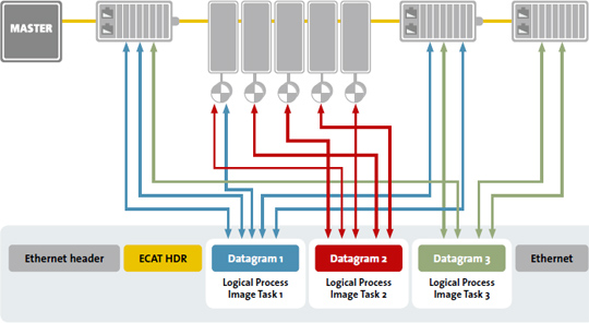
Inserting process data on the fly
In addition to logical addressing, the MainDevice can also address a SubDevice via its position in the network. This method is used during network boot up to determine the network topology and compare it to the planned topology.
After checking the network configuration, the MainDevice can assign each node a configured node address and communicate with the node via this fixed address. This enables targeted access to devices, even when the network topology is changed during operation, for example with Hot Connect Groups. There are two approaches for SubDevice-to-SubDevice communication. A SubDevice can send data directly to another SubDevice that is connected further downstream in the network. Since EtherCAT frames can only be processed going forward, this type of direct communication depends on the network’s topology, and is particularly suitable for SubDevice-to-SubDevice communication in a constant machine design (e.g. in printing or packaging machines). In contrast, freely configurable SubDevice-to-SubDevice communication runs through the MainDevice, and requires two bus cycles (not necessarily two control cycles). Thanks to EtherCAT’s excellent performance, this type of SubDevice-to-SubDevice communication is still faster than with other communication technologies.
1.3 Flexible Topology
Line, tree, star, or daisy-chain: EtherCAT supports almost all of topologies. EtherCAT makes a pure bus or line topology with hundreds of nodes possible without the limitations that normally arise from cascading switches or hubs.
When wiring the system, the combination of lines with drop lines is beneficial: the ports necessary to create drop lines are directly integrated in many I/O modules, so no additional switches or active infrastructure components are required. The star topology, the Ethernet classic, can also naturally be utilized.
Modular machines or tool changers require network segments or individual nodes to be connected and disconnected during operation. EtherCAT SubDevice controllers already include the basis for this Hot Connect feature. If a neighboring station is removed, then the port is automatically closed so the rest of the network can continue to operate without interference. Very short detection times < 15 μs guarantee a smooth changeover.
EtherCAT offers a lot of flexibility regarding cable types, so each segment can use the exact type of cable that best meets its needs. Inexpensive industrial Ethernet cable can be used between two nodes up to 100m apart in 100BASE-TX mode. Furthermore, the protocol addition EtherCAT P enables the transmission of data and power via one cable. This option enables the connection of devices such as sensors with a single line. Fiber Optics (such as 100BASE-FX) can also be used, for example for a node distance greater than 100m. The complete range of Ethernet wiring is also available for EtherCAT.
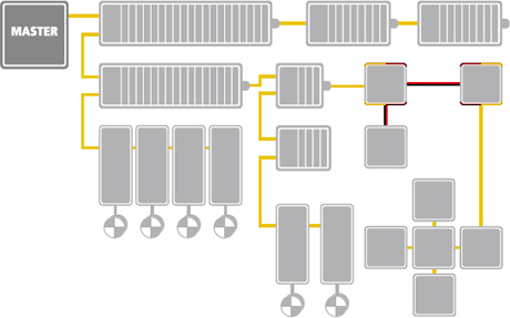
Flexible topology – line, tree or star
Up to 65,535 devices can be connected to one EtherCAT segment, so network expansion is virtually unlimited. Because of the practically unlimited number of nodes, modular devices such as “sliced” I/O stations can be designed in such a way that each module is an EtherCAT node of its own. Hence, the local extension bus is eliminated; the high performance of EtherCAT reaches each module directly and without any delays, since there is no gateway in the bus coupler or head station any more.
1.4 EtherCAT P: communication and power in one cable
EtherCAT P (P = power) is an addition to the previously described EtherCAT protocol standard. It enables not only the transmission of communication data, but also the peripheral voltage via a single, standard four-wire Ethernet cable.
EtherCAT and EtherCAT P are identical in terms of the protocol technology, as the addition exclusively affects the Physical Layer. No new EtherCAT SubDevice Controllers are necessary when using EtherCAT P. One could say that EtherCAT P has the same communication advantages as EtherCAT, but also provides the power supply via the communication cable, offering attractive benefits and enhancements for numerous applications.
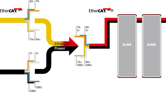
EtherCAT P: data and power via one cable
Two electrically isolated, individually switchable 24V supplies power the new EtherCAT P devices, available with US serving the system and sensors and UP serving the periphery and actuators. Both voltages, US and UP, are directly coupled into the 100Mbit/s EtherCAT communication line. Thanks to this power transmission, the user can cascade several EtherCAT P devices and therefore only needs one cable. This facilitates reduced cabling, more compact, cost-effective wiring, lower system costs and a smaller footprint for devices, equipment and machines.
EtherCAT P is especially interesting for those parts of a machine that are self-contained and often a bit isolated, as they can be supplied with data and power through a single stub cable. Sensors of all types are perfectly suitable for EtherCAT P: a single compact M8 connector enables efficient integration of these field devices into the high-speed network and connects them to the supply voltage. Potential error sources while connecting devices are avoided, thanks to mechanical coding of the connector.
EtherCAT P can be used in the same network together with standard EtherCAT technology. Appropriate rectifier units transform common EtherCAT physics to EtherCAT P by consistently maintaining the Ethernet data encoding. In the same way, a device itself can be supplied with EtherCAT P but, in turn, can also transmit the EtherCAT protocol.
Read more...
1.5 Distributed Clocks for High-Precision Synchronization
In applications with spatially distributed processes requiring simultaneous actions, exact synchronization is particularly important. For example, this is the case for applications in which multiple servo axes execute coordinated movements.
In contrast to completely synchronous communication, whose quality suffers immediately from communication errors, distributed synchronized clocks have a high degree of tolerance for jitter in the communication system. Therefore, the EtherCAT solution for synchronizing nodes is based on such distributed clocks (DC).
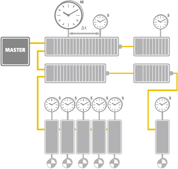
Completely hardware-based synchronization with compensation for propagation delays.
The calibration of the clocks in the nodes is completely hardware-based. The time from the first DC SubDevice is cyclically distributed to all other devices in the system. With this mechanism, the SubDevice clocks can be precisely adjusted to this reference clock. The resulting jitter in the system is significantly less than 1μs.
Since the time sent from the reference clock arrives at the SubDevices slightly delayed, this propagation delay must be measured and compensated for each SubDevice in order to ensure synchronicity and simultaneousness. This delay is measured during network startup or, if desired, even continuously during operation, ensuring that the clocks are simultaneous to within much less than 1μs of each other.
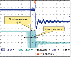
Synchronicity and simultaneousness – scope view of two distributed devices with 300 nodes and 120 m cable length
If all nodes have the same time information, they can set their output signals simultaneously and affix their input signals with a highly precise timestamp. In motion control applications, cycle accuracy is also important in addition to synchronicity and simultaneousness. In such applications, velocity is typically derived from the measured position, so it is critical that the position measurements are taken precisely equidistantly (i.e. in exact cycles). Even very small inaccuracies in the position measurement timing can translate to larger inaccuracies in the calculated velocity, especially relative to short cycle times. With EtherCAT, the position measurements are triggered by the precise local clock and not the bus system, leading to much greater accuracy.
Additionally, the use of distributed clocks also unburdens the MainDevice; since actions such as position measurement are triggered by the local clock instead of when the frame is received, the MainDevice doesn’t have such strict requirements for sending frames. This allows the MainDevice stack to be implemented in software on standard Ethernet hardware. Even jitter in the range of several microseconds does not diminish the accuracy of the Distributed Clocks! Since the accuracy of the clock does not depend on when it’s set, the frame’s absolute transmission time becomes irrelevant. The EtherCAT MainDevice needs only to ensure that the EtherCAT telegram is sent early enough, before the DC signal in the SubDevices triggers the output.
1.6 Diagnosis and Error Localization
Experience with conventional fieldbus systems has shown that diagnostic characteristics play a major role in determining a machine’s availability and commissioning time. In addition to error detection, error localization is important during troubleshooting. EtherCAT features the possibility to scan and compare the actual network topology with the planned topology during boot up. EtherCAT also has many additional diagnostic capabilities inherent to its system.
The EtherCAT SubDevice Controller in each node checks the moving frame for errors with a checksum. Information is provided to the SubDevice application only if the frame has been received correctly. If there is a bit error, the error counter is incremented and the subsequent nodes are informed that the frame contains an error. The MainDevice will also detect that the frame is faulty and discard its information. The MainDevice is able to detect where the fault originally occurred in the system by analyzing the nodes’ error counters. This is an enormous advantage in comparison to conventional fieldbus systems, in which an error is propagated along the entire party line, making it impossible to localize the source of the error. EtherCAT can detect and localize occasional disturbances before the issue impacts the machine’s operation.
Thanks to EtherCAT’s unique principle of bandwidth utilization, which is orders of magnitude better than industrial Ethernet technologies that use single frames, the likelihood of disturbances induced by bit errors within an EtherCAT frame is substantially lower – if the same cycle time is used. And, if in typical EtherCAT fashion much shorter cycle times are used, the time required for error recovery is significantly reduced. Thus, it is also much simpler to master such issues within the application.
Within the frames, the Working Counter enables the information in each Datagram to be monitored for consistency. Every node that is addressed by the Datagram and whose memory is accessible increments the Working Counter automatically. The MainDevice is then able to cyclically confirm if all nodes are working with consistent data. If the Working Counter has a different value than it should, the MainDevice does not forward this Datagram’s data to the control application. The MainDevice is then able to automatically detect the reason for the unexpected behavior with help from status and error information from the nodes as well as the Link Status.
Since EtherCAT utilizes standard Ethernet frames, Ethernet network traffic can be recorded with the help of free Ethernet software tools. For example, the well-known Wireshark software comes with a protocol interpreter for EtherCAT, so that protocol-specific information, such as the Working Counter, commandos, etc. are shown in plain text.
EtherCAT Diagnosis for Users
EtherCAT Diagnosis for Developers
1.7 High Availability Requirements
For machines or equipment with very high availability requirements, a cable break or a node malfunctioning should not mean that a network segment is no longer accessible, or that the entire network fails.
EtherCAT enables cable redundancy with simple measures. By connecting a cable from the last node to an additional Ethernet port in the MainDevice, a line topology is extended into a ring topology. A redundancy case, such as a cable break or a node malfunction, is detected by a software add-on in the MainDevice stack. That’s all there is to it!
The nodes themselves don’t need to be modified, and don’t even “know” that they’re being operated in a redundant network.
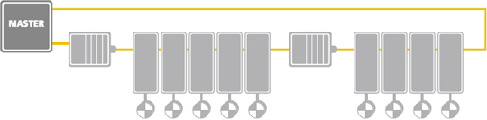
Inexpensive cable redundancy with standard EtherCAT SubDevices
Link detection in the SubDevices automatically detect and resolve redundancy cases with a recovery time is less than 15 μs, so at maximum, a single communication cycle is disrupted. This means that even motion applications with very short cycle times can continue working smoothly when a cable breaks.
With EtherCAT, it’s also possible to realize MainDevice redundancy with Hot Standby. Vulnerable network components, such as those connected with a drag chain, can be wired with a drop line, so that even when a cable breaks, the rest of the machine keeps running.
1.8 Safety over EtherCAT
Modern communication systems not only realize the deterministic transfer of control data, they also enable the transfer of safety-critical control data through the same medium. EtherCAT utilizes the protocol Safety over EtherCAT (FSoE = Fail Safe over EtherCAT) for this very purpose and so allows:
- A single communication system for both control and safety data
- The ability to flexibly modify and expand the safety system architecture
- Pre-certified solutions to simplify safety applications
- Powerful diagnostic capabilities for safety functions
- Seamless integration of the safety design in the machine design
- The ability to use the same development tools for both standard and safety applications
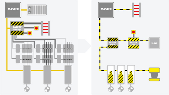
Safety over EtherCAT enables simpler and more flexible architectures than with relay logic
The EtherCAT safety technology was developed according to IEC 61508, is approved by TÜV Süd Rail, and is standardized in IEC 61784-3. The protocol is suitable for safety applications with a Safety Integrity Level up to SIL 3.
With Safety over EtherCAT, the communication system is part of a so-called Black Channel, which is not considered to be safety relevant. The standard communication system EtherCAT makes use of a single channel to transfer both standard and safety-critical data. Safety Frames, known as Safety Containers, contain safety-critical process data and additional information used to secure this data. The Safety Containers are transported as part of the communication’s process data. Whether data transfer is safe does not depend on the underlying communication technology, and isn’t restricted to EtherCAT; Safety Containers can travel through fieldbus systems, Ethernet or similar technologies, and can make use of copper cables, fiber optics, and even wireless connections.
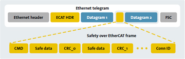
The Safety Container is embedded in the cyclical communication’s process data
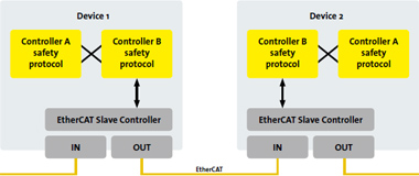
Due to this flexibility, safely connecting different parts of the machine becomes more simple. The Safety Container is routed through the various controllers and processed in the various parts of the machine. This makes emergency stop functions for an entire machine or bringing targeted parts of a machine to a standstill easily possible – even if the parts of the machine are coupled with other communication systems (e.g. Ethernet).
Implementing the FSoE protocol in a device requires little resources and can lead to a high level of performance and correspondingly, short reaction times. In the robotics industries, there are applications that use SoE for safe motion control applications in an 8-kHz closed loop.
Black-Channel-Principle: the standard communication interface can be used
Further information regarding Safety over EtherCAT can be found on the ETG website:
www.ethercat.org/safety
1.9 Communication Profiles
In order to configure and diagnose SubDevices, it is possible to access the variables provided for the network with the help of acyclic communication. This is based on a reliable mailbox protocol with an auto-recover function for erroneous messages.
In order to support a wide variety of devices and application layers, the following EtherCAT communication profiles have been established:
- CAN application protocol over EtherCAT (CoE)
- Servo drive profile, according to IEC 61800-7-204 (SoE)
- Ethernet over EtherCAT (EoE)
- File Access over EtherCAT (FoE)
- Automation Device Protocol over EtherCAT (ADS over EtherCAT, AoE)
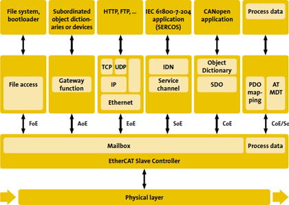
Different communication profiles can coexist in the same system
A SubDevice isn’t required to support all communication profiles; instead, it may decide which profile is most suitable for its needs. The MainDevice is notified which communication profiles have been implemented via the SubDevice description file.
1.9.1 CAN application protocol over EtherCAT (CoE)
With the CoE protocol, EtherCAT provides the same communication mechanisms as in CANopen®-Standard EN 50325-4: Object Dictionary, PDO Mapping (Process Data Objects) and SDO (Service Data Objects) – even the network management is similar. This makes it possible to implement EtherCAT with minimal effort in devices that were previously outfitted with CANopen®, and large portions of the CANopen® Firmware are even reusable. Optionally, the legacy 8-byte PDO limitation can be waived, and it’s also possible to use the enhanced bandwidth of EtherCAT to support the upload of the entire Object Dictionary. The device profiles, such as the drive profile CiA 402, can also be reused for EtherCAT.
1.9.2 Servo drive profile according to IEC 61800-7-204 (SoE)
SERCOS™ is known as a real-time communication interface, especially for motion control applications. The SERCOS™ profile for servo drives is included in the international standard IEC 61800-7. The standard also contains the mapping of this profile to EtherCAT. The service channel, including access to all drive-internal parameters and functions, are mapped to the EtherCAT Mailbox.
1.9.3 Ethernet over EtherCAT (EoE)
EtherCAT makes use of physical layers of Ethernet and the Ethernet frame. The term Ethernet is also frequently associated with data transfer in IT applications, which are based on a TCP/IP connection.
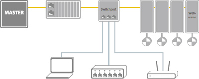
Transparent transmission of standard IT protocols
Using the Ethernet over EtherCAT (EoE) protocol any Ethernet data traffic can be transported within an EtherCAT segment. Ethernet devices are connected to an EtherCAT segment via so-called Switchports. The Ethernet frames are tunneled through the EtherCAT protocol, similarly to the internet protocols (e.g. TCP/IP, VPN, PPPoE (DSL), etc.) as such, which makes the EtherCAT network completely transparent for Ethernet devices. The device with the Switchport property takes care of inserting TCP/IP fragments into the EtherCAT traffic and therefore prevents the network’s real-time properties from being affected.
Additionally, EtherCAT devices may also support Ethernet protocols (such as HTTP) and can therefore behave like a standard Ethernet node outside of the EtherCAT segment. The MainDevice acts as a Layer-2-switch that sends the frames via EoE to the corresponding nodes according to their MAC addresses. In this way, all internet technologies can also be implemented in an EtherCAT environment, such as an integrated web server, E-mail, FTP transfer, etc..
1.9.4 File access over EtherCAT (FoE)
This simple protocol similar to TFTP (Trivial File Transfer Protocol) enables file access in a device and a uniform firmware upload to devices across a network. The protocol has been deliberately specified in a lean manner, so that it can be supported by boot loader programs – a TCP/IP stack isn’t required.
1.9.5 ADS over EtherCAT (AoE)
As a Mailbox-based client-server protocol, ADS over EtherCAT (AoE) is defined by the EtherCAT specification. While protocols such as CAN application protocol over EtherCAT (CoE) provide a detailed semantic concept, AoE complements these perfectly via routable and parallel services wherever use cases require such features. For example, this might include access to sub-networks through EtherCAT using gateway devices from a PLC program such as CANopen®, IO-Link™ and others.
AoE comes with far less overhead when compared with similar services provided by the Internet Protocol (IP). Both sender and receiver addressing parameters are always contained in the AoE telegram – as a result, a very lean implementation on both ends (client and server) is possible. AoE is also the protocol of choice for acyclic communication via the EtherCAT Automation Protocol (EAP) and therefore provides seamless communication between an MES system, the EtherCAT MainDevice, and subordinated fieldbus devices connected via gateways. AoE serves as the standard means to obtain EtherCAT network diagnostic information from a remote diagnostics tool.
1.10 Plant-wide communication with the EtherCAT Automation Protocol (EAP)
The process management level has special communication requirements that differ slightly from the requirements addressed by the EtherCAT Device Protocol, described in the previous sections. Machines or sections of a machine often need to exchange status information and information about the following manufacturing steps with each other. Additionally, there is usually a central controller that monitors the entire manufacturing process, which provides the user with status information on productivity, and assigns orders to the various machine stations. The EtherCAT Automation Protocol (EAP) fulfills all of the above requirements.
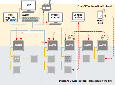
Factory-wide Communication with EtherCAT
The protocol defines interfaces and services for:
- Exchanging data between EtherCAT MainDevices (MainDevice-MainDevice communication),
- Communication to Human Machine Interfaces (HMI),
- A supervising controller to access devices belonging to underlying EtherCAT segments (Routing),
- Integration of tools for the machine or plant configuration, as well as for device configuration.
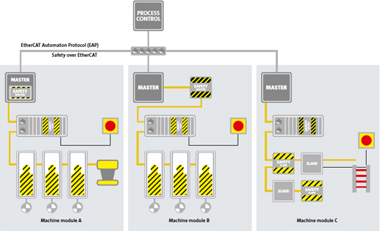
Factory-wide communication architecture with the EtherCAT Automation Protocol and Safety over EtherCAT
The communication protocols used in EAP are part of the international standard IEC 61158. EAP can be transmitted via any Ethernet connection, including a wireless link, for example making it possible to include automated guided vehicles (AGV), which are common in the semiconductor and automotive industries.
Cyclic process data exchange with EAP follows either the „Push“ or „Poll“ principle. In “Push” mode, each node sends its data either with its own cycle time or in a multiple of the own cycle time. Each receiver can be configured to receive data from specific senders. Configuring the sender and receiver data is done through the familiar Object Dictionary. In “Poll” mode, a node (often the central controller) sends a telegram to the other nodes, and each node responds with its own telegram.
The cyclic EAP communication can be directly embedded within the Ethernet frame, without additional transport or routing protocol. Again, the EtherType Ox88A4 identifies the EtherCAT specific use of the frame. This enables the exchange of high-performance data with EAP in a millisecond cycle. If data routing between distributed machines is required, the process data can also be transmitted via UPD/IP or TCP/IP.
Additionally, with the help of the Safety over EtherCAT Protocol, it’s also possible to transmit safety-critical data via EAP. This is common in cases where parts of a large machine need to exchange safety-critical data to realize a global emergency stop function, or to inform neighboring machines of an emergency stop.
1.11 Integration of other Bus Systems
EtherCAT’s ample bandwidth makes it possible to embed conventional fieldbus networks as an underlying system via an EtherCAT Gateway, which is particularly helpful when migrating from a conventional fieldbus to EtherCAT. The changeover to EtherCAT is gradual, making it possible to continue using automation components that don’t yet support an EtherCAT interface.
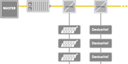
Decentralized fieldbus interfaces
The ability to integrate decentralized gateways also reduces the physical size of the Industrial PC, sometimes even to an embedded Industrial PC, since extension slots are no longer necessary. In the past, extension slots were also required to connect complex devices, such as fieldbus MainDevice and SubDevice gateways, fast serial interfaces, and other communication subsystems. In EtherCAT, all that is needed to connect these devices is a single Ethernet port. The process data from the underlying subsystem is made directly available in the process image of the EtherCAT system.
1.12 Powering the digital transformation with EtherCAT, TSN, Industrie 4.0 and IoT
Process optimizations, predictive maintenance, manufacturing as a service, adaptive systems, resource-savings, smart factories, cost reductions – there are countless good reasons to utilize control network data in higher level systems. The Internet of Things (IoT), Industrie 4.0, Made in China 2025, Industrial Value Chain Initiative: there is a common need across the board for seamless, continuous and standardized communication across all levels. Sensor data uploaded into the cloud along with recipes and parameters downloaded from ERP systems into distributed devices; take, for example, a feeding system shared by two machines: there are data flow requirements both in vertical and horizontal directions. EtherCAT inherently meets the requirements of the digital transformation through its high performance, flexibility and open interfaces: Superior system performance is the prerequisite for adding Big Data features to control networks.
EtherCAT provides the flexibility to add cloud connectivity to existing systems without even touching the controller or updating the SubDevices: Edge Gateways can access any data within any EtherCAT SubDevice via the Mailbox Gateway feature of the EtherCAT MainDevice. The Edge Gateway can either be a remote device, talking to the MainDevice via TCP or UDP/IP, or a software entity directly located on the same hardware as the EtherCAT MainDevice itself.
Additionally, open interfaces allow one to integrate any IT-based protocol – including OPC UA, MQTT, AMQP or any others – either within the MainDevice or directly into the SubDevices, thus providing a direct link for IoT without protocol discontinuities from the sensor to the cloud.
All these features have always been part of the EtherCAT protocol, which shows how forward-thinking the architecture is. Nevertheless, more networking features are added as they evolve and become relevant. Of course, it is also important to consider the past when looking forward: this introduction of valuable new features is managed with total network continuity as the EtherCAT protocol itself has been stable at “Version 1” since its introduction in 2003.
Other new developments in the area of Time Sensitive Networking (TSN) features further improve the real-time capabilities of the Controller to Controller communication. Enabled by TSN, control systems - even those that are cloud-based – can access a network of EtherCAT SubDevices also across plant networks. Since EtherCAT typically only needs one frame for an entire network, such access is much leaner and thus faster than any other fieldbus or industrial Ethernet technology. In fact, EtherCAT Technology Group experts have contributed to the TSN task group of IEEE 802.1 from day one – at a time when TSN was still known as AVB.
The EtherCAT Technology Group (ETG) was also among the first fieldbus organizations to partner with the OPC Foundation. The OPC UA protocol complements the EtherCAT portfolio because it is a scalable TCP/IP based client/server communication technology with integrated security, enabling encrypted data transfer up to MES/ERP systems. With OPC UA Pub/Sub, the usability of OPC UA has been improved in machine-to-machine (M2M) applications and for vertical communication to cloud based services. The ETG is actively contributing to all these developments to ensure that they fit seamlessly into the EtherCAT environment.
Therefore, EtherCAT is not only IoT-ready, EtherCAT is IoT!
Read more about EtherCAT & TSN...
![]()
EtherCAT technology has been specially optimized to enable low-cost design, so adding an EtherCAT interface to a sensor, I/O device, or embedded controller should not significantly increase device costs. Furthermore, the EtherCAT interface also doesn’t require a more powerful CPU- the CPU requirements instead are based only on the needs of the target application.
In addition to hardware and software requirements, development support and the availability of communication stacks are important when developing an interface. The EtherCAT Technology Group offers worldwide developer support in quickly answering questions or addressing technical issues. Finally, evaluation kits available from multiple manufacturers, developer workshops, as well as free sample code make getting started a little easier.
For the end user, the most important factor is the interoperability of EtherCAT devices from various manufacturers. To ensure interoperability, device manufacturers are required to perform a Conformance Test prior to bringing their device on the market. The test checks if the implementation follows the EtherCAT specification, and can be performed with the EtherCAT Conformance Test Tool. The test can also be used during device development to discover and correct implementation issues early on.
2.1 MainDevice
The interface for an EtherCAT MainDevice has a single, unbelievably simple, hardware requirement: an Ethernet port. The implementation uses either the on-board Ethernet controller or an inexpensive standard network card, so no special interface card is required. That means that with just a standard Ethernet port, a MainDevice can implement a hard real-time network solution.
In most cases the Ethernet controller is integrated via Direct Memory Access (DMA), so no CPU capacity is required for the data transfer between the MainDevice and the network. In an EtherCAT network, mapping occurs at the SubDevices. Each SubDevice writes its data to the right location in the process image and reads the data addressed to it all while the frame is moving through. Therefore, the process image that arrives at the MainDevice is already sorted correctly.
Since the MainDevice CPU is no longer responsible for the sorting, its performance requirements depend only on the desired application and not the EtherCAT interface. Especially for small, mid-sized, and clearly defined applications, implementing an EtherCAT MainDevice is a snap. EtherCAT MainDevices have been implemented for a wide variety of operating systems: Windows and Linux in various iterations, QNX, RTX, VxWorks, Intime, eCos are just a few examples.
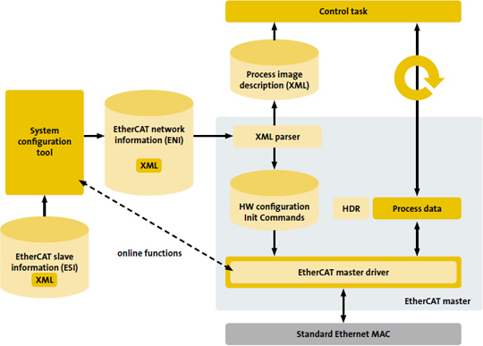
Typical EtherCAT MainDevice Architecture
ETG members offer a variety of options to support the implementation of an EtherCAT MainDevice, ranging from free downloads of EtherCAT MainDevice Libraries, sample MainDevice code, all the way to complete packages (including services) for various real-time operating systems and CPUs.
In order to operate a network, the EtherCAT MainDevice requires the cyclic process data structure as well as boot-up commands for each SubDevice. These commands can be exported to an EtherCAT Network Information (ENI) file with the help of an EtherCAT configuration tool, which uses the EtherCAT SubDevice Information (ESI) files from the connected devices.
The breadth of available MainDevice implementations and their supported functions varies. Depending on the target application, optional functions are either supported or purposely omitted to optimize the utilization of hardware and software resources. For this reason, EtherCAT MainDevices are categorized into two classes: a Class-A-MainDevice is a standard EtherCAT MainDevice, while a Class-B-MainDevice is a MainDevice with fewer functions. In principle, all MainDevice implementations should aim for Class A classification. Class B is only recommended for cases in which the available resources are insufficient to support all functionalities, such as in embedded systems.
2.2 SubDevice
EtherCAT SubDevices use inexpensive EtherCAT SubDevice Controllers (ESC) in the form of an ASIC, FPGA, or integrated in a standard microcontroller. Simple SubDevices don’t even need an additional microcontroller, because inputs and outputs can be directly connected to the ESC. For more complex SubDevices, the communication performance depends only minimally on the microcontroller performance, and in most cases, a 8-bit microcontroller is sufficient.
EtherCAT SubDevice Controllers are available from multiple manufacturers, with the size of the internal DPRAM and the number of Fieldbus Memory Management Units (FMMUs) depending on the variation. Different Process Data Interfaces (PDI) for external access from the application controller to the application memory are also available:
- The 32-Bit parallel I/O Interface is suitable for connecting up to 32 digital inputs and outputs, but also for simple sensors or actuators for which 32 data bits are sufficient and no application controller is required.
- The Serial Peripheral Interface (SPI) is targeted at applications with small amounts of process data, such as analog I/O devices, encoders, or simple drives.
- The parallel 8/16-Bit Microcontroller Interface corresponds to common interfaces of fieldbus controllers with integrated DPRAM. It is particularly suitable for complex nodes with larger amounts of data.
- Suitable synchronous busses for various microcontrollers have been implemented for FPGA and On-Chip variations.
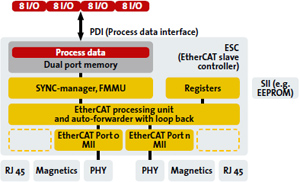
SubDevice Hardware: EtherCAT SubDevice Controller with direct I/O
The hardware configuration is stored a in non-volatile memory (e.g. an EEPROM), the SubDevice Information Interface (SII), which contains information about the basic device features, so that the MainDevice can read this at boot-up and operate the device even if the device description file is not available. The EtherCAT SubDevice Information (ESI) file that comes with the device is XML based and contains the complete description of its network accessible properties, such as process data and their mapping options, the supported mailbox protocols including optional features, as well as the supported modes of synchronization. The Network Configuration Tool uses this information for online and offline configuration of the network.
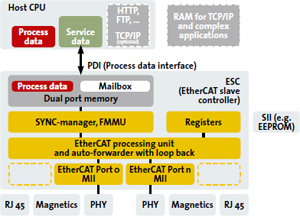
SubDevice Hardware: EtherCAT SubDevice Controller with Host CPU
Various manufacturers offer evaluation kits for implementing SubDevices. These kits include SubDevice application software in source code, and they sometimes also include a test MainDevice. Using an evaluation kit, a fully functional MainDevice-SubDevice EtherCAT network can be commissioned in just a few steps. The ETG website contains a SubDevice Implementation Guide with useful tips and hints on further documentation for implementing SubDevices:
ETG.2200 EtherCAT and EtherCAT P SubDevice Implementation Guide
Two important factors for a communication standard to be successful are conformance and interoperability. In addition to requiring a conformance test for each device implementation (aided by the automated EtherCAT Conformance Test Tool), the EtherCAT Technology Group offers a variety of activities to ensure the interoperability between EtherCAT MainDevices, SubDevices, and also the EtherCAT Configuration Tool.
Read more...
3.1 Plug Fest
When trying to test if multiple devices are interoperable, connecting the devices together is a pragmatic approach. With this in mind, the ETG holds multiple so called Plug Fests each year, with each Plug Fest usually spanning two days. During the Plug Fests, MainDevice and SubDevice manufacturers come together to test how their devices behave together, which improves the usability of devices in the field. The ETG holds Plug Fests in Europe, North America, and Asia on a regular basis.
Read more...
3.2 Conformance Test Tool (CTT)
The EtherCAT Conformance Test Tool (CTT) makes it possible to automatically test an EtherCAT SubDevice’s behavior. The CTT is a Windows program requiring only a standard Ethernet port. The tool sends EtherCAT frames to the Device under Test (DuT) and receives its responses. A test case is marked as passed if the response from the DuT corresponds to the defined response. The test cases are defined as XML files. This makes it possible to modify or expand the test cases without having to modify the actual test tool. The TWG Conformance is responsible for specifying and releasing the most current valid test cases. In addition to the protocol tests, the CTT also examines if the values in the EtherCAT SubDevice Information (ESI) file are valid. Finally, the CTT also performs device-specific protocol tests, such as for the CiA402 drive profile. All of the testing steps and results are saved in a Test Logger, and can be analyzed or saved as a documented verification for the device release.
Read more...
3.3 Technical Working Group Conformance
The EtherCAT Conformance Test Policy requires device manufacturers to test each device with a valid version of the EtherCAT Conformance Test Tool before the device is brought on the market. The manufacturer may conduct this test in-house. The ETG Technical Committee (TC) established a Technical Working Group (TWG) Conformance, which determines the test procedures, the contents of the test, and the implementation of the Conformance Test Tool. The TWG Conformance is continuously expanding the tests and their depth. The TWG Conformance also established an Interoperability Tests process, with which devices can be tested in the context of an entire network.
Read more...
3.4 EtherCAT Test Center
The official EtherCAT Test Centers (ETC) in Europe, Asia and North America are accredited by the ETG and perform the official EtherCAT Conformance Test. The EtherCAT Conformance Test includes the automated tests run with the CTT, interoperability tests within a network, as well as an examination of the device’s indicators, markings, and tests of the EtherCAT interfaces.
Device manufacturers are encouraged but not obligated to have their devices tested at an ETC. After the Conformance Test is passed, the manufacturer receives an EtherCAT Conformance Tested certificate for the device. This certificate is only available for devices that have passed the Conformance Test at an ETC- not for those which have been tested in-house.
The additional test in an accredited EtherCAT Test Center further increases compatibility and the uniform operation and diagnostics of EtherCAT implementations. End users should be sure to ask for the EtherCAT Conformance Tested certificate when choosing devices for their application.
Read more...
The EtherCAT Technology Group is an official partner of the IEC. Both EtherCAT and Safety over EtherCAT are IEC-Standards (IEC 61158 and IEC 61784). These standards not only include the lower protocol layers, but also the application layer and device profiles, e.g. for drives. SEMI™ (Semiconductor Equipment and Materials International) has accepted EtherCAT as a communication standard (E54.20) for the semiconductor industry. The various Task Groups in the ETG Semiconductor Technical Working Group (TWG) have defined industry specific device profiles and implementation guidelines. The EtherCAT Specification is available in English, Japanese, Korean, and Chinese.

EtherCAT Brochure
Learn more about the fastest "Ethernet fieldbus" in detail:
English
German
Spanish
Italian
French
Chinese
Japanese
Korean
EtherCAT Multimedia
EtherCAT in 2 minutes:
Watch full playlist

EtherCAT Functional Principle:
Processing on the fly

EtherCAT in 20 minutes:
Generating competitive advantages

SPS IPC Drives 2018:
15 years of ETG

HANNOVER MESSE 2016:
Toyota selects EtherCAT